TL;DR
- What is quantum error correction?
Quantum error correction protects quantum information by encoding one logical state across several physical qubits. The system measures error syndromes, then uses those syndromes to infer and correct likely faults.
- How does quantum error correction work in practice?
A device repeatedly measures stabilizers with ancilla qubits. A classical decoder interprets the syndrome pattern and chooses a correction or updates a Pauli frame, while the encoded logical state remains unmeasured.
- How does quantum error correction differ from classical error correction?
Classical error correction can copy bits. Quantum computing error correction cannot clone arbitrary unknown states, so it creates entangled codewords and measures parity-like observables that reveal errors without revealing the logical state.
- What are the main challenges in implementing quantum error correction?
Major challenges include physical error rates, qubit overhead, correlated faults, leakage, fast repeated measurement, decoder latency, logical-gate fidelity, and the control hardware needed to coordinate large numbers of qubits.
- How does the Willow chip improve quantum error correction?
Google’s 105-qubit Willow generation improved qubit lifetimes and system-level gate performance enough to demonstrate surface-code error suppression as code distance increased. Its distance-7 logical memory outlived its best constituent physical qubit.
- How does Willow achieve below threshold quantum error correction?
Willow combines improved physical qubit performance, repeated surface-code stabilizer measurements, calibrated control, and classical decoding. Google measured a logical error-suppression factor above two when increasing code distance from smaller to larger lattices.
- What did Gil Kalai say about quantum error correction?
Kalai argues that realistic correlated noise can prevent scalable quantum error correction from satisfying the assumptions required by threshold theorems. His position is disputed, and modern experiments such as Willow test whether larger codes can reduce logical errors in real hardware.
- What is a stabilizer quantum error correction?
Stabilizer quantum error correction defines valid code states through commuting Pauli operators. Measuring those stabilizers reveals syndrome changes caused by errors while preserving the encoded logical information inside the code space.
Table of Contents
Quantum information creates an apparent contradiction. A quantum computer must detect errors, but measuring an unknown qubit can destroy the superposition it is trying to preserve. The no-cloning theorem also prevents the computer from making perfect backup copies of an arbitrary unknown quantum state.
Quantum error correction gets around this problem by spreading information across several physical qubits and measuring only how they relate to one another.
In this guide, we’ll walk you through everything you need to know about quantum error correction.
Here’s what we cover:
- What is quantum error correction?
- Why can’t quantum computers use classical error correction?
- How does quantum error correction work without collapsing the quantum state?
- Foundational quantum error correction codes (worked examples)
- How does surface code quantum computing scale logical qubits?
- What are the breakthroughs and challenges in quantum error correction?
What Is Quantum Error Correction?
Quantum error correction (or QEC) is a family of methods that protects quantum information from noise and decoherence by spreading one fragile quantum state across many physical qubits so that errors can be detected and corrected.
Because quantum bits (qubits) are extremely sensitive to interference and cannot be cloned or measured without collapsing their states, QEC uses mathematical codes to achieve fault-tolerant computing.
- A physical qubit is a raw hardware component (such as a superconducting circuit, trapped ion, or neutral atom) that stores quantum information, while a logical qubit is an error-corrected virtual qubit created by grouping and entangling multiple physical qubits.
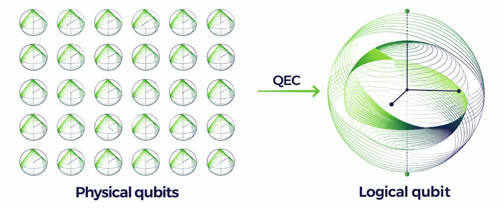
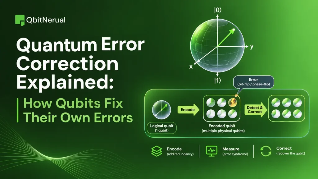
Quantum error correction for beginners in simple terms. Quantum error correction protects quantum information by spreading one logical qubit into several physical qubits in an entangled state. Ancilla qubits check for errors by measuring error syndromes. A classical decoder uses these syndromes to choose how to correct the errors. This can detect and fix faults without copying or directly reading the protected quantum information.
“Twenty-first century computers could achieve astonishing speed by exploiting the principles of quantum mechanics. New techniques of quantum error correction will be essential to prevent those machines from crashing.” — John Preskill, Nature, 1998.
Why Can’t Quantum Computers Use Classical Error Correction?
Classical systems protect data by copying bits and using majority voting. For example, if a single bit is copied three times as 000 and one copy changes (noise flips one bit and 0 becomes 1), the computer can infer the value from the other two (takes a majority vote) and correct the error.
Quantum systems cannot use that strategy because the laws of quantum mechanics prevent copying an unknown state perfectly, and measurement changes the information being protected.
No-cloning theorem and measurement collapse
The no-cloning theorem states that you cannot duplicate an arbitrary unknown quantum state. You cannot simply clone a fragile qubit to create a backup. Quantum error correction instead creates an encoded entangled state, distributing the logical information to several qubits without producing independent clones.
For example, the encoding:
does not produce three copies of . It creates one three-qubit entangled state whose two logical basis states are and . The amplitudes and remain properties of the joint state.
In addition to the no-cloning theorem, you cannot measure the qubits to check for errors. If you measure the data qubits to check for errors, you instantly destroy the superposition and the calculation you are trying to protect.
Consider an unknown state:
A direct measurement in the computational basis forces the qubit to choose a side, returning either 0 or 1 with probabilities determined by the amplitudes. Once measured, the original coherent superposition is permanently destroyed. Direct measurement reveals information about the logical value at the absolute cost of disturbing and collapsing the state.
Quantum error correction avoids that problem by measuring observables that distinguish error subspaces without distinguishing the logical states within the code space. The measurement can answer whether an expected parity relation has changed while leaving and hidden.
Bit-flip vs. phase-flip errors (and continuous errors)
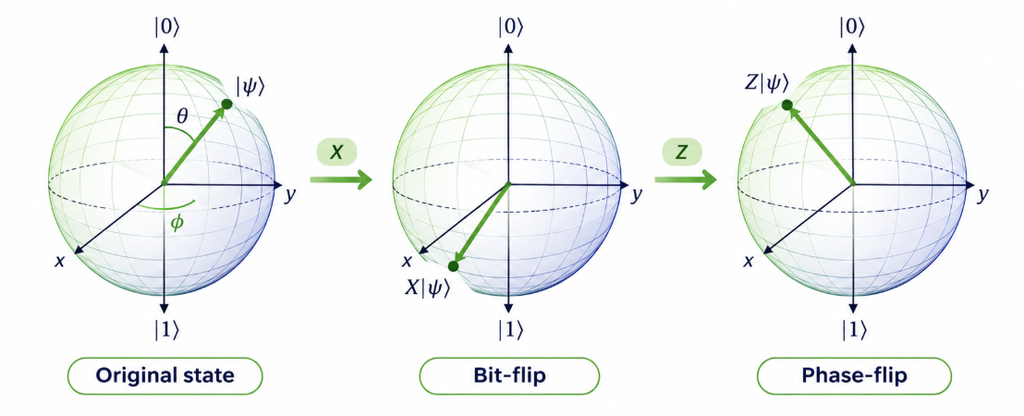
Classical bits suffer from one type of error, bit-flips (0 becoming 1). Qubits suffer from two Pauli error types: bit-flips and phase-flips (where the mathematical sign of the quantum wave changes), creating complex, continuous errors that a simple classical majority vote cannot detect.
- A bit-flip uses the Pauli (X) operator:
- A phase flip uses the Pauli (Z) operator:
Applying both produces a (Y)-type error, up to an overall phase.
Real noise is not limited to neat discrete flips. A qubit can undergo a small unwanted rotation, amplitude damping, dephasing, or a correlated interaction with nearby qubits. Stabilizer-based quantum error correction remains powerful because general single-qubit errors can be expanded in the Pauli operator basis, allowing the quantum error correction codes to diagnose discrete syndromes associated with those components.
How Does Quantum Error Correction Work Without Collapsing the Quantum State?
To fix faults without destroying data, use clever circuit designs that rely on entanglement and parity checks. The following steps explain how quantum error correction works.
Step 1: Encode one logical qubit across multiple physical qubits
First, the system must encode the data. Instead of copying a state, the hardware uses entangling gates to spread one logical qubit’s information across a larger framework of physical qubits.
For example, a basic protocol encodes one logical qubit into three physical qubits. The system does not create three independent copies. Instead, it creates a single entangled state where the information lives in correlations between the physical qubits rather than in any individual physical particle.
Step 2: Use ancilla qubits to measure parity
To check for errors without measuring the data qubits, the system introduces helper components known as ancilla qubits.
An ancilla qubit acts as a temporary scratchpad. The quantum computer applies controlled gates (like CNOT gates) between the data qubits and the ancilla qubit. These gates transfer parity information (whether two data qubits hold the same state or different states) onto the ancilla.
Because the system only measures the ancilla qubit, it only extracts the parity relationship. Measuring the ancilla does not reveal whether the encoded logical state is , , or a superposition of both. It only reveals whether the data qubits agree or disagree with each other.
Step 3: Extract the error syndrome without reading the logical information
The result of the ancilla measurement is called an error syndrome. The error syndrome provides a unique digital fingerprint that identifies which physical qubit suffered a quantum error.
Scientists achieve this through stabilizer measurements. A stabilizer is an operator that leaves the logical codespace unchanged but flags anomalies when violated.
Consider the parity checks Z1Z2 and Z2Z3:
- The Z1Z2 operator checks if qubit 1 and qubit 2 share the same bit value.
- The Z2Z3 operator checks whether qubit 2 and qubit 3 share the same bit value.
If a thermal fluctuation flips qubit 1, the Z1Z2 measurement result changes from an expected state of agreement (+1 eigenvalue) to disagreement (-1 eigenvalue). A changed measurement result signals a violation of an expected parity relation, alerting the system to the exact location of the fault.
Step 4: Decode the syndrome and recover the logical state
Syndrome extraction simply outputs classical binary data. Decoding is the classical computational process that interprets that data.
A classical decoder reads the syndrome string and selects a likely correction. If the syndrome reads that qubit 1 and 2 disagree, but qubit 2 and 3 agree, the decoder uses logic to deduce that qubit 1 must have flipped.
The control hardware then applies the corresponding recovery operation, sending a microwave pulse to apply an X gate to qubit 1 and return it to its correct state. The recovery process need not identify the exact microscopic fault. The recovery operator cancels out the discrete Pauli fault mapped by the syndrome.
What Are the Quantum Error Correction Codes and How Do They Work?
Quantum error correction codes differ in what errors they correct, how many physical qubits they require, and how difficult they are to implement fault tolerantly. Early repetition-style codes are easy to understand by hand, while stabilizer and topological codes provide the formal structure used in modern architectures.
The 3-Qubit Bit-Flip Repetition Code
The 3-qubit bit-flip repetition code provides the simplest manual example of encoding, parity checking, and recovery. It protects against bit flips but cannot correct phase flips.
The system encodes a logical as and a logical as . Imagine the system encodes an unknown state . A noise event causes a bit-flip on the first physical qubit. The state becomes .
To detect this, the system uses two ancilla qubits to measure the parity between adjacent data qubits.
- The Z1Z2 check compares the first and second qubits. Because they now differ, the ancilla measurement yields a -1 (a classical binary 1).
- The Z2Z3 check compares the second and third qubits. Because they remain identical, the ancilla yields a +1 (a classical binary 0).
The resulting syndrome is 10. The classical decoder interprets this specific syndrome as a bit-flip on qubit 1. The control system applies an X gate to qubit 1. The state returns perfectly to , leaving the amplitudes completely undisturbed.
Expanding to Phase Flips and the Shor Code
The 3-qubit code fails if a phase flip occurs. The 9-qubit Shor code emerged as the first framework capable of correcting both bit and phase flips simultaneously.
The Shor code elegantly concatenates two layers of protection. It first encodes the logical state against phase flips using a 3-qubit phase-flip code. It then takes each of those three physical qubits and encodes them again using a 3-qubit bit-flip code. This requires nine physical qubits in total. If any single qubit suffers an X, Z, or combined Y error, the nested parity checks isolate the exact location and type of the fault, allowing full recovery.
Introduction to Stabilizer Quantum Error Correction
Transitioning from manual parity checks to formal frameworks required mathematical rigor. The stabilizer quantum error correction formalism utilizes group theory to manage parity checks efficiently.
Instead of tracking the massive state vector of a multi-qubit system, the stabilizer formalism tracks only the Pauli operators that leave the logical codespace unchanged. A prominent example is the [[5,1,3]] code, the smallest code that can correct any single-qubit error, which uses four specific stabilizing generators to protect one logical qubit with just five physical qubits. This mathematical abstraction lets engineers simulate large codes systematically and design automated decoder software.
How Does Surface Code Quantum Computing Scale Logical Qubits?
While early codes proved correction was physically possible, wiring physical qubits together in complex concatenations creates severe hardware bottlenecks. To scale up, the industry shifted toward topological frameworks.
Surface codes are among the most studied architectures for large-scale fault-tolerant quantum computing. They use local stabilizer measurements on a two-dimensional arrangement of qubits and can tolerate relatively high physical error rates under appropriate noise models. Their layout matches the local connectivity available in many superconducting-qubit platforms.
How Does Surface Code Quantum Error Correction Work?
Surface code quantum computing currently stands as the industry standard for 2D qubit layouts. The architecture arranges physical qubits on a flat, two-dimensional checkerboard grid.
In this structure, data qubits sit on the grid vertices, while measure qubits (ancillas) sit inside the square plaquettes. Half of the measure qubits perform X-type parity checks to detect phase flips, and the other half perform Z-type parity checks to detect bit flips.
Crucially, the surface code only requires nearest-neighbor interactions. Each ancilla qubit interacts only with the four data qubits immediately adjacent to it. Circuit diagrams for surface code cycles reveal a highly repeatable, tiled pattern of CNOT gates that easily scales across a large silicon wafer, making it the preferred architectural blueprint for quantum hardware development.
What Are Code Distance, Error Thresholds, and Logical Error Rates?
To understand how topological codes scale, engineers rely on three critical metrics: code distance, error thresholds, and logical error rates.
- Code Distance (d): The distance of a code determines how many faults it can tolerate. A distance-d code corrects up to (d-1)/2 physical errors. In the rotated surface code, a distance-d logical qubit requires 2d2-1 physical qubits in total (d2 data qubits and d2-1 measurement qubits). A larger distance provides a stronger protective shell.
- Error Threshold: The technical threshold acts as a fundamental tipping point. If the underlying physical qubits are highly noisy (above threshold), adding more qubits to the surface code introduces more faults than the code can fix, degrading performance. However, if the physical error rate drops below the critical threshold (roughly 1% for the surface code), scaling up the distance works as intended. Below threshold, adding more physical qubits exponentially suppresses the overall error rate.
- Logical Error Rates: This metric defines the probability that the protected logical qubit fails during one complete cycle of error correction. Performance is often measured by the suppression factor, which quantifies how much the logical error drops as the code distance increases.
“There is no point in doing quantum error correction if you aren’t below threshold.” — Julian Kelly, Google’s Director of Quantum Hardware.
What Are the Latest Breakthroughs and Challenges in Quantum Error Correction?
Quantum computing error correction has moved toward experiments that compare logical and physical error rates, perform real-time decoding, and integrate logical encoding into larger computations. But the challenge remains which is fault-tolerant machines need enough qubits, control bandwidth, decoder speed, and logical-gate fidelity to outperform direct physical computation.
The IBM Quantum Error Correction Experiment
IBM has explored alternatives to the standard surface code because its requirement for qubits to connect only with nearby qubits (strict 2D locality) can demand a large number of physical qubits. Recent work has focused on quantum low-density parity-check (qLDPC) codes.
The most notable IBM quantum error correction experiment used the “gross code,” a [[144, 12, 12]] bivariate bicycle code. It stores 12 logical qubits using 288 physical qubits. Achieving the same level of protection with surface codes would require nearly 3,000 physical qubits, so the qLDPC code uses about one-tenth as many (a factor of ten).
But qLDPC codes are harder to connect across a chip because they need links between qubits that may be far apart. To decode these non-local structures, IBM developed the Relay-BP decoder, which runs on FPGA hardware and completes each belief-propagation step in 24 nanoseconds.
Advancing the Quantum Error Correction 2026 Processor
Hardware scaling will shape quantum computing over the next two years, and quantum error correction 2026 processors have to handle extra parity checks with low-latency decoding.
Google’s Willow chip leads this wave. It is a 105-qubit superconducting processor built with optimized cryogenic infrastructure. Willow has longer coherence times, with T1 relaxation times of about 100 microseconds (~5x improvement over the previous generation of chips).
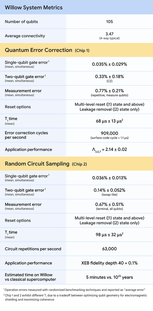
Furthermore, Willow manages data qubit leakage removal (DQLR) on the chip. This helps stop continuous noise from corrupting parity rounds. When a qubit state leaks out of the computational basis, it can cause cascading faults called hook errors. Willow’s leakage removal (DQLR) helps decoders keep up with cycles as short as 1.1 microseconds.
Similarly, Quantinuum has also made progress with its Helios trapped-ion processor. Using color codes, Quantinuum achieved 99.9995% logical memory fidelity, proving that differing qubit modalities offer unique advantages in all-to-all connectivity and baseline physical fidelity.
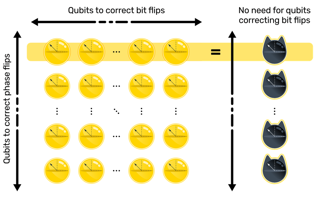
Meanwhile, Alice & Bob use bosonic “cat qubits,” which naturally reduce bit-flip errors in hardware. This can greatly reduce the extra resources needed for later phase-flip correction.
Achieving Quantum Error Correction Below the Surface Code Threshold
Reducing error rates below the threshold is the milestone where scaling up physical qubits can improve the accuracy of logical qubits.
In late 2024, Google Quantum AI published research detailing quantum error correction below the surface code threshold on the Willow processor. The team measured a logical error rate of 0.14% per cycle using a distance-7 surface code. Increasing the code distance reduced errors by a factor of 2.14 each time. In other words, moving from distance 3 to 5, and then to 7, cut the logical error rate by more than half at each step.
“We are finally below the threshold.” — Michael Newman, a research scientist at Google Quantum AI.
Willow’s logical memory also passed the “breakeven” point. It lasted 2.4 times longer than the best physical qubit used to build it. The system maintained this performance with a real-time decoder that took 63 microseconds to process information. Furthermore, the team also demonstrated magic state cultivation on the chip, reducing errors in complex non-Clifford gates by a factor of 40.
Despite these empirical successes, some researchers remain skeptical.
“Fully Depolarizing Noise Conjecture for Entangled Physical States.” — Gil Kalai
While challenges like cosmic ray impacts and heat dissipation in cryogenic CMOS controllers persist, recent demonstrations increasingly validate the theoretical scaling models, cementing a clear path toward fault-tolerant computation.
Conclusion
Quantum error correction cannot rely on copying information or directly measuring qubits. Instead, it protects logical qubits by encoding information across multiple physical qubits, measuring error syndromes, and applying corrections without disturbing the protected quantum state.
Simple quantum error correction codes, such as the three-qubit repetition code and Shor code, demonstrate how this process works. More advanced approaches, including stabilizer codes and surface code quantum computing, extend these principles to larger systems.
Recent breakthroughs from Google, IBM, and other quantum hardware developers show measurable progress toward practical error correction. Google’s Willow processor demonstrated that increasing surface-code distance can reduce logical error rates below the threshold, while IBM’s qLDPC research explores ways to reduce the physical-qubit overhead.
However, challenges remain in hardware noise, qubit connectivity, real-time decoding, and scaling. The next major goal is to create logical qubits that become more reliable as error correction scales. Achieving that goal will bring quantum computing closer to running complex calculations accurately and consistently.